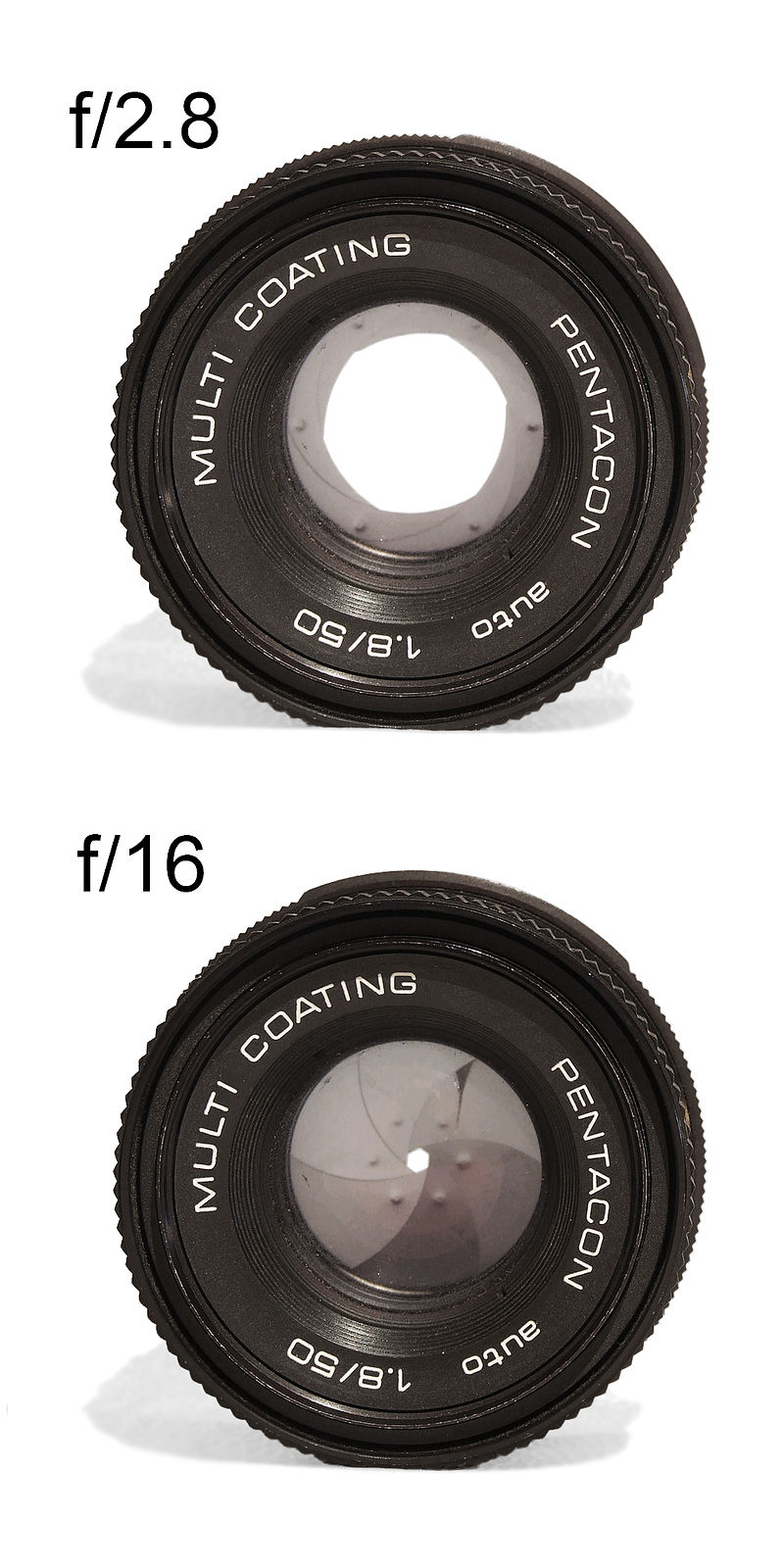
When you look at the lens from the front you see an aperture.

Many people think what they see is the mechanical iris, but instead it is just “the image of the iris as seen through the object side lenses”, or short “
entrance pupil”.

A (non mirror) object point sends light in all directions .. (proof: both of your eyes can see the object point, as also all people in the room in a suitable position can see it).
If by at this position there is a lens, also ALL points of the front surface of the lens will get light from this object point.
Not all light will reach the pixel though … only the light that fits through the entrance pupil.
The above holds for ALL object points.
This means however that ALL object points send
light in all directions and SHARE the
entrance pupil!!!!
This means, btw, that if there is a little dust particle or mini air bubble on the front
lens that is 1/1000 of the
entrance pupil area, it will reduce the brightness of ALL image points by 1/1000 , say, it’s
not visible on the sensor / monitor.
That’s why inspecting lenses with a microscope is, say, less useful 🙂
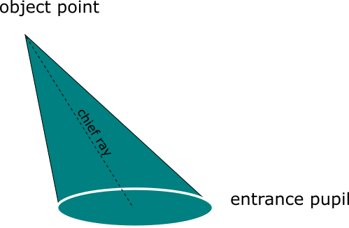
The axis of this (elliptical (!) ) cone , say, “the line between an object point and the CENTER of the
entrance pupil” has a shorter name : (object side)
chief ray.
So
Each object point has an (object side)
chief ray and we will learn that each Pixel / image point) has a (image side)
chief ray too.
But careful :
Each object point has a
chief ray, say,
for each object point there is corresponding a chief ray angle. We’ll learn that every pixel / image point has an individual chief ray angle too.
When we talk of THE (object side) chief ray angle , we in fact mean the (object side( maximum chief ray angle.
This (object side) CRA is used to define viewing angles :

The viewing angles are measured from the
entrance pupil center (the point where all chiefrays meet) to two points on your object.
For the horizontal viewing angle these are the horizontal left and right objectside points just visible on the screen.
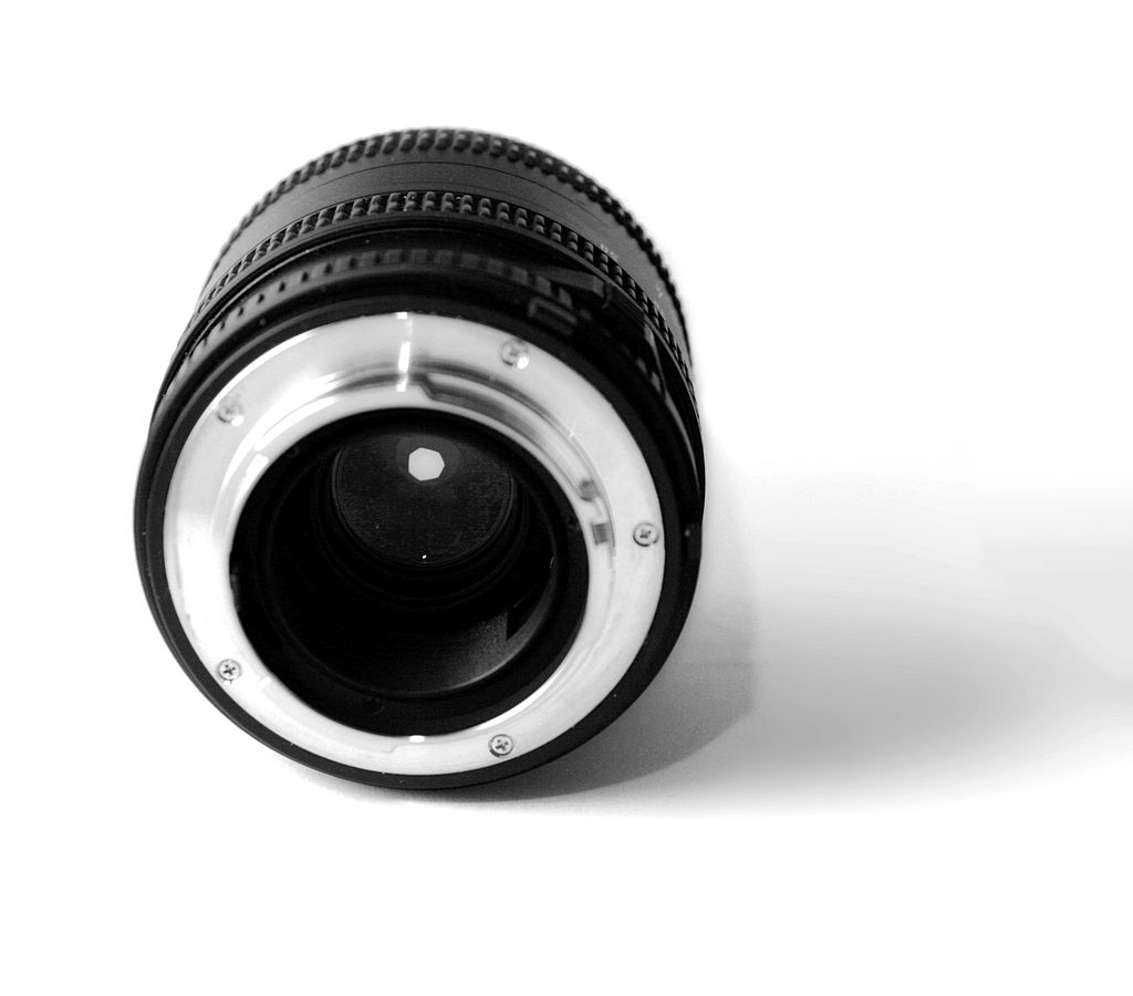
When you look at the lens from the image side , you see this :

We see an aperture. And again its not the iris, but “the image of the mechanical iris as seen through all glass elements on image side”
or short the “
exit pupil”
You can guess the rest :
The light for each pixel will use the WHOLE exit pupil and concentrate on one circle (called Airy disk)

If there is a sensor and the airy disk is small enough, you see a focussed pixel.
The angle between the
optical axis and each the (millions of) chief rays is called
(image side) chief ray angle.
So if we use
CRA , we mean the (image side)
chief ray angle , say, the maximum of all chiefray of all pixels.
These usually occur in the corners of the sensor.
If you have a look at the drawings one thing is important :
The
chief ray connects the object point with the center of the
entrance pupil. But from the object point also
light with steeper and shallower angles than the
CRA will arrive at the pixel !!!!

Which angles exactly occur is objeviously determined by the diameter of entrance and
exit pupil, and we remember that these are IMAGES of the physical iris
With the physical iris its images, say, the pupils, and thius the off-chief-
ray-angles get smaller.
If the maximum is zero so all other values must be zero too.
Such lenses are called (object or image side)
telecentric lenses, and the only possible explanation how all rays from the center of pupil can arrive at zero degrees is that the pupil is at infinity !
Telecentric lenses have (like all other lenses) an entrance and
exit pupil of non zero diameter (else no
light would arrive at the pixel).
The maximum image side angle (
larger than the CRA, btw. !!! ) is given by the angles from the rim of the
exit pupil to the pixels.
So even for lenses with
CRA 0,
light arrives at larger off axis angles than zero, say, at larger angles than the
CRA.
If the
CRA is non zero .. for example (image side)
CRA=15°,
light will arrive at various off axis angles at the sensor .. for example always at zero degrees right on the
optical axis.
However the
CRA is NOT the maximum angle that the
light will arrive at the (corner) pixels.
Because , again, the angles between the
CRA and the connection of all points on the
exit pupil rim to the pixel have to be added.
On the object side, the situation is like this:

The situation is the reverse position of the image side CRA:
Just exchange entrance with exit and object point with image point.
At the pixels rays will arrive with shallower and with steeper angles than the
CRA.
If the opening angle of the cone is, say, 10 degrees, then angles at
CRA+5° and Angles at
CRA – 5° will also arrive.
For a
CRA° of 15 and a cone angle of ,say, 20°, angles between 5° (=15°-10°) and 25° (= 15° + 10° ) will occur.
If the sensor is prepared for this , fine.
What happens, when the CRA is too big or too small for a sensor?
When we’re off the acceptable angle of the sensor pixels this
light may of may not hit insensitive parts of pixel structures (and we’d get some
vignetting) or (likewise unpleasant) the
light will land in the neighbour pixel and make it brighter .. which would cost a bit of local
contrast.
Sensor manufacturwer often tell you the accepted position and diameter (say, indirectly the cone angle) that the sensor is made for.


