Category Archives: Practice

What happens when you focus lenses from infinity to shorter distances?

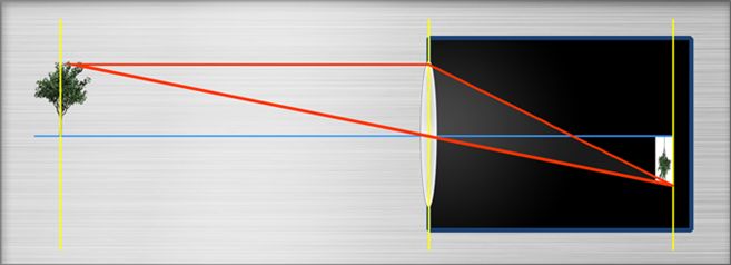
To focus on shorter distances, s-mount lenses have to be “unscrewed” . On first glance this seems to be very different from larger Lenses like C- or CS-mount Lenses, that provide a focus ring. If the focusing ring is turned however also in larger lenses the position of a lens package from the sensor is increased. (There are a few exception of lenses that offer more than one lens package that are moved synchrously, one of this maybe towards the sensor) .
Well over 95% of all lenses work as described here:

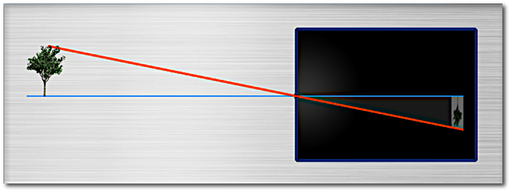
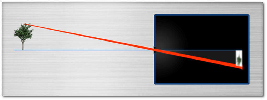
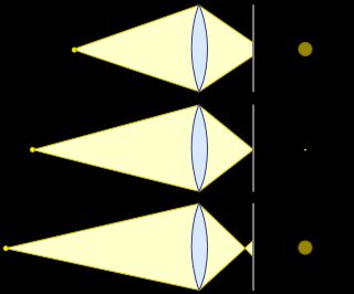
May the lens be focussed on infinity. What happens when you increase the distance of the lens package from the sensor, for example by unscrewing or by turning the focus ring?

  • The _maximum_ object side viewing angle of the lens stays the same… because the optics does not change
  • The _maximum_ image side viewing angle of the lens stays the same… because the optics does not change
  • The _maximum_ amount of pixels the lens can handle is still the same … because the optics does not change
  • The F# changes to the “Working F#” (also called effective F#) :
    The F# of a lens is only defined for infinite distance. When focused to infinity the focal point of the lens is right on the sensor.The F# is then defined as : Focal length, divided by the Entry-Pupil-Diameter (= the appearant diameter of the “hole”  in the lens when you look from object side = “EPD”)The working F# (‘wF#) is defined a little different : wF# = (focal length + amount unscrewed) /EPD = F# + (amount unscrewed / EPD)
In the general case, that the Magnification is M ( where M = sensor size / object size) we get a formula :

    \[wF\# = (1 + M) * F\#\]

Example 1:
For a 1:1 magnification (object size = sensor size), you have to unscrew by the focal length. 12mm for a 12mm lens : 4mm for a f=4mm lens , 50mm for a 50mm lens)
For the 1:1 case we get

    \[wF\# = 2* F\#\]

(because the amount unscrewed = f , so we get

    \[wF\# = 2 * (focal length / EPD ) = 2*F\# \]

)
We get the same result from the above formula with M=1 :

    \[wF\# = 2 F\#\]

Example 2:
For the object at infinity, no unscrewing is needed, so we have wF# = F#.
The magnification for objects at infinity is zero, because the sensor is small and at infinite distances the lens sees infinite much. (Hundreds of galaxies at the night sky, for example). So we get from the formula above :

    \[wF\# = (1 + M) F\# = (1 + 0)F\# = F\#\]

  • The brightness of the image changes:
    The amount of light that reaches the sensor is determined by wF#, the working F#. wF# depends on the diameter of the Entry pupil, but the brightness depends on the area of the entry pupil.
When the wF# is increased by factor x, the image brightnness is decreased by factor x^2
Brightness of a standard 1:1 lens:
wF#, the working F# of a 1:1 lens is
wF# = 2 F# = twice the wF# at infinity \]
So the brightness decreases by factor 2^2 = 4 compared to the brightness at infinity
  • In general the resolution decreases: The smallest possible point diameter that a diffraction limited (read”perfect”) lens can generate is given by the Rayleigh diameter :

        \[ D = 2 * 1.22 * wF\# * Wavelength \]

    The resolution is half that diameter R = D/2.

The resolution of a (non telecentric) 1:1 lens is about half the resolution of the lens in infinity position , both in x and y direction. If the lens could resolve 5 Megapixel at infinity before, the resolution drops to 1.3 Megapixel if it is used in an 1:1 setup.
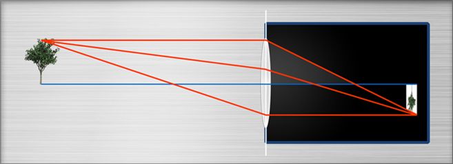
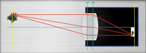
    • The Field of view gets smaller: Because the lens is not telecentric (but “entocentric”), the light arrives at some Angle > 0 in the corners of the sensor. We can imagine this as an image side (half) viewing angle. That angle is called (max) Chief ray angle) When the lens is in infinity position. When we increase the distance to the sensor, tha maximum angle stays the same, but some of the light will no longer reach the sensor. This means, only a smaller fan angle on image side can be used. This implicated that also only a smaller angle on object side can be used!
    • The magnification changes. This is because the sensor keeps its size and the visible Object size gets smaller, see above
    • The distortion in general gets better : Distortion of each lens is larger in the corners of the field of view than in the center. Because we use a smaller object and image side angle now, we also don’t use the old colrners of the image any more. Therefore we don’t use the rim of the lens elements
    • There working distance changes, because the ratio of object distance and image distance is the Magnification, which changed.
    • The Chief Ray Angle CRA changes. This it the off axix angle at which the light arrives in the sensor corners.
Sensors with shifted microlenses can have troubles with short workingdistances if they need a minimum CRA. Microlens-Vignetting would be the result
Lenses that were designed for infinity, assume that the light arrives about parallel at the lens. This clearly defines angles at with the light arrives at the sensor surface.
By changing the working distance from infinity to a shorter distance, maybe even below the MOD, these angles change. But for these new angles the lens was never designed, so the performance MUST suffer.
Whether the performance is still good enough depend on you application and especially on the sensor pixel size
Telecentric lenses behave different: The image side F# is Magnification times the object side F#.
For an 1:1 lens for example is the imageF# = object side F#, the resolution on image and object side is the same (and not factor 2 lower than with entocentric lenses. Also the image brightness does not decrease by factor 4.

About the Sense and Nonsense of Resolution

Resolution

What is it in general?

Resolution describes in general the ability of a “system” to provide “details”. Systems can be anything, a thermometer , a speedometer in a car, a TV screen, a printer, … and last but not least cameras and lenses.

resolution

How much resolution makes sense?

When people talk about cameras, easily a Megapixel race starts. The general optinion in the consumer market may be “the more, the better”.

Marketing is the big player behind the scenes.  If my competitor offers 1 Mega-something and I can offer two Mega-something, this is usually reason enough for the subconcious mind of the consumer to go for the higher number.

All depends on the information we need. If we are interested in the position of the Alpes with an accuracy of +/-100km , the right image above definitely has enough resolution. No need for a map with a resolution that shows individual cars.

Do we need to know the temperature with a resolution of 1/100 degree?

For half a century a VGA TV resolution (640×480 pixels) was just fine for us to get the “needed” information. These days HDTV and 4K resolution is  a must. Again .. it’s nice to have, but is it needed?

A strange phenomenon in terms of resolution are  ..

Desktop printers: They once offered like 200dpi .. some offer 9.600dpi these days.
dpi is short for “dots per inch”. It does not mean however that a printer could print 1/200th  of an inch thin lines then nor 1/9600th of an inch wide lines now!

Resolution comes at a cost

When a new TV with extra high resolution appears at the market, the prices are very high. This is because the manufactures obviously  can  sell it at that price and because the development costed lots of money.

Once this new resolution becomes standard, the prices drop considerably.
But as long as its not mass product:

High resolution = higher precision, better production machines, better inspection tools, better workers, .. needed, maybe even brand new production strategies)As a result: Low volume production -> high prices

In our daily lives we learnt:

  • Media with higher writing speed need a new media writer
  • Media with higher capacity, BlueRay  disks etc, need needs a special player
  • Highres lossless sound recordings need more space

The “hidden” costs of high sensor resolution:

  • Highres Cameras need much better lenses.
  • Highres cameras need a faster interface to the computer
  • As the bandwidth (=pixels per second) of an interface is limited, if the number of pixels grows by a factor, the frames per second go down by this factor.
  • When we can get color images the same resolution as greyscale images before, the software got to be adapted.
  • If we there are more pixels per image, we have to process more pixels, if there are more frames per second, we have to process more frames per second. A faster software, a faster computer, even a better programmer might be needed.
  • With shrinking pixel sizes, the “noise” increases. Algorithms might have to be adapted to the previously absent noise, additional light sources might be necessary to provide enough light for a low noise image.
  • With shrinking pixel sizes, the light sensitivity is reduced, which might cause problems in dusk and dawn.
  • As color images in general work with a  ratio Red :  Green: Blue, special care has to be taken about sensor noise,  as this influences the ratios, say, the colors.
  • The higher the resolution, the more difficult it is to have a high “local contrast”.

Contrast:

The optical term contrast of an image is pretty much what we would expect from our daily use of the word.

contrast1

However, we have to distinguish global contrast
contrast2
… from local contrast :
local contrast

The global contrast in the two images above is about the same, however the local contrast (the change from pixel to pixel) is less high in the lower image, because of the slight blurring.

The limits of resolution:

Lens resolution limits:

Apart from the production quality, the resolution of a lens is limted by a physical effect called “diffraction”.
The “best possible” lenses are called “diffraction limited”, read : they are as good as allowed by physics … “only limited by diffraction”.
In short, diffraction is an (unexpected) change in direction of light particles that occurs if they don’t have neighbors “travelling” in the same direction. As a result diffraction occurs at the rim of a lens iris, at the surface of metal rods, threads etc.

The degree of diffraction depends on the amount of “rim” compared to the “clear” area.
The area of a circle is A = PI * radius * radius.
The length of the circumference of a circle is R = 2 * PI * radius.
So Rim / Area = R / A = (2 * PI * radius) / (PI * radius * radius) = 2/radius
Say, the smaller the radius, the more influence has the rim, compared to the center.Also, the higher the energy of the light, the less diffraction occurs. Say, blue light has a lower diffraction than red light and red has a lower diffraction than infrared light.
According to the “Rayleigh Criterion” the smallest dot a diffraction limited lens can generate has a diameter of
D = 2 * 1.22 * wavelength * F#
The resolution of such a lens is R = 1.22 * wavelength * F# at about 20% contrast.
For a wavelength of 400nm we get (for 400nm light)
D = 2 * 1.22 * wavelength * F# = 2 * 1.22 * 400nm * F# = 976nm * F#
As 1000nm = 1um, we get as a rule of thumb D = F# um , say, the F# in micrometers.
Accordingly we get as resolution (for 400nm light and 20% contrast) R = 1.22 * wavelength * F# = 1.22 * 400nm * F# = 488nm * F# , say “half the F#” in micrometers
For a wavelength of 800nm we get (for 800nm light)
D = 2 * 1.22 * wavelength * F# = 2 * 1.22 * 800nm * F# = 1952nm * F#
As 1000nm = 1um, we get as a rule of thumb D = 2*F# um , say, two times the F# in micrometers.
Accordingly we get as resolution (for 800nm light and 20% contrast) R = 1.22 * wavelength * F# = 1.22 * 800nm * F# = 976nm * F# , say “the F#” in micrometers

As a side result we notice :

The best possible resolution of a lens by physics depends (linearly) on the wavelength : double wavelength = double size of the smallest details that can be resolved
One way to achieve a better resolution it to use a smaller wavelength for the lens design (i.e. 440nm blue instead of 660nm red or 660nm red instead of 890nm infrared.

For diffraction limited lenses with an F# below the optimal aperture : The higher the F#, the higher is the DOF, the lower the resolution and thus the lower is the local contrast (= lower MTF) .
If lenses are not diffraction limited, increasing the F# makes means using more the center parts of the lens elements (which have lower aberrations). Therefore the resolution increases for a while until the critical aperture is reached, then it decreases.

Why Megapixel? Lenses don’t have a Pixel-Structure after all!

Some centuries ago, people noticed with some surprise, that in a dark room sometimes an (upside down) image of the environment is projected across a small opening in a wall.
The old latin word for room (chamber) is camera.
That’s why the first cameras got the name “camera obscura” ( = “dark chamber”). One of the first real-life-applications was portrait painting.

CameraObscura

The same principle is used in so called “pinhole-cameras”:
camera_obscura

Its immediately clear, why the image is upside down.
The advantage is however, that the Image is were it would be mathematically expected. There is no distortion ! (rectangles on object side becomae rectangles on image side). There’s no visible dependency from the wavelength. The depth of Field is infinitely large.
The disadvantage is that the resulting image is very dark, (so the room must be even darker for the image to be seen at all. The needed exposure times to take an image with todays cameras could well be minutes!

Idea: Lets use a larger hole :

large_hole_camera_obscura

Now, however, the image not only gets brighter (as intended) but also gets blurry, because the light not only passes through the center of the hole. So not only the correct position of the image is exposed to the light, but also the direct neighbours.

As a result, the image of an object point is not just a point, but instead a little disk, the so called “Circle of Confusion” (CoC).

For long distance objects the diameter of the CoC equal the diameter of the hole!
For short distance objects, even larger. Read, the “resolution” is very bad.

Whish: Each image point shall be just a mathematical point and not a circle.

Idea: lets place a biconvex (“collecting lens”) lens into the hole:

collecting-lens.in-iris

Note: every point of the front lens is reached by light from the object.

How to predict what size the image will have and where the position of the Images of object points is?

Two simple rules apply:

Image construction:
Rays through the center of the lens pass straight through the lens.
Rays arriving parallel to the optical axis and through the object point are “bent” through the focal point of the lens.
Where these two rays meet, is the image of the object point.

We note:

All object points on the plane perpendicular to the optical axis (the “object plane”) are mapped to another plane perpendicular to the optical axis, the “image plane”.
Image-plane

If image and object distnces are given, we can calculate the focal length of the lens.
This appoach is used in all them focal length calculators online.

In real life, we notice a slight difference between the theoretical values and the real distances:
thick-lens-mapping

Due to this difference between theory and parctice :

All focal length calculators that ignore the thickness of the lens give just approximate results, especially in short distances and for wide angles

But even the model of the thick lenses (the “paraxial image model”) works with

Implicite assumptions:
The lenses are perfect, say don’t have optical aberrations.
In case of the thin lenses : all lenses are infinitely thin.
Monochrome light is used.
The model assumes sin(x) = x, which is an approximation that holds only very close to the optical axis.

There’s good and bad news :

Good news: The Circle of Confusion (“CoC”) can be drastically reduced by the use of collecting lenses

We also notice that :
Objects at different distances result in CoCs of different size.
The “acceptable” maximal size of the CoC thus results in the so called “depth of field
CoC

Bad news: The Circle of Confusion (“CoC”) can not become arbitrarily small. It willl always stay a disk and never becomes a mathematical point.

Say : there are no perfect lenses. (even if they could be produced arbitrarily accurate)

The theoretical size of the smallest CoC possible even for close to perfect lenses , so called diffraction limited lenses) is described by the so called Rayleigh criterion.

Rule of Thumb:
For white light it’s not possible to generate CoCs smaller than the F# measured in micrometers.
The theoretical resultution is half thatvalue
A diffraction limited lens of F#4 can not generaqte image points smaller than 4um in diamter.
The theoretical best resultion is 4um / 2 = 2um
An image appears focussed, if the CoC is smaller than the pixel structure of the sensor.
See also Why can color cameras use lower resolution lenses than monochrome cameras?.

If the image can appear focussed on a sensor with n megapixels, then the lens is classified as an n Megapixel lens

Keep in mind that the Megpixel refer to the maximum image circle that a lens has. If a sensor uses just 50% of the area of image circle, only half the pixels are supported.
If a 5 Megapixel 1″ lens (i.e. image circle 16mm) is used on a 1/2″ sensor (image circle 8mm) one should not expect a resolution bettern than 1.3 (!) Megapixels. This is because the area of a 1/2″ sensor is 1/4 (!) of the area of an 1″ sensor!. So you lose factor 4 of the Megapixels.

Can I increase the DOF by changing the focal length, if FOV and brightness are constant?

Per Definition
DOF := Far PointNear Point.

The formulas for these are really complicated and contain several times the focal length.

Surprisingly, despite the formulas given there:

The focal length has no influence on the DOF if FOV and F\# are constant.

in other words :

As long as FOV and F# are both constant, the DOF is the same from whatever distance.

Because the brighness shall stay the same, the F# is the same.
Because the FOV is the same, also the Magnification \beta is the same for both lenses.

Because the F# is the same, also the NA (Numerical Aperture) is the same.
This is because F\# = \frac{1}{2*NA(image side)}.
As NA = \sin(\alpha), also the angle \alpha doesn’t change.

Our definition of sharpness, the allowed circle of confusion, of course shall not change.

Also, due to the Rayleigh Criterion, the resolution of the lenses is the same (assuming lenses of the same, diffraction limited excellent quality).

So if we have a close look at the location where the light gathers for one pixel, we see ..

SVG of Diffraction at Pixel Level

Diffraction at pixel Level

The red disk shows the smallest Airy disk Possible, according to Rayleigh – controlled only by Wavelength and F\#. (See Rayleigh Criterion). The diameter is (according to Rayleigh) twice the lens’ resolution.
The green disk is the user’s definition of “is still focussed”. As the angle \alpha is constant, so is 2 \alpha, which is the opening angle of the double cone at pixel level.
As angle and slimmest part of the double cone are the same, so is the upper and lower point where the Green disk touches. The distance of upper and lower max. point of the green disk is the image side Depth of Focus. The object side DOF (depth of field) is Depth of Focus / Magnification \beta, which is constant, because the FOV is constant.