Category Archives: Uncategorized

The DOF is too small, what can I do?

For some applications a certain depth of field (DOF) is given. Objects at different distances have to be focused at the same time.

We have calculator for this, see Calculator for given DOF

This calculator tells you interactively what parameters will influence your DOF, and so far how many percent of the wanted DOF you achieved already.

There are just three parameters that influence the DOF:

  • focal length (indirectly given if you have sensor size, working distance and field of view (FOV)
  • CoC (the circle of maximum confusion describes you definitiion of the diameter of the light disk (instead of a mathematical point) that you still call focused. A typical measure here is
    CoC = 4 times the pixel size. So by choosing the sensor you indirectly choose the CoC too
  • F-Number : The higher the F-Number, the higher the DOF. Nice. However : The Rayleigh Criterion tell us that a higher F-Number can also descrease the resolution.

High DOF and high resolution contradict!

So we see, there is not too much freedom.

What if we need high resolution AND a high DOF ?
Things depend if you have time. if you have time, you could take a series of pictures in different distances, using focus modules , for example from https://www.piezolution.com/.
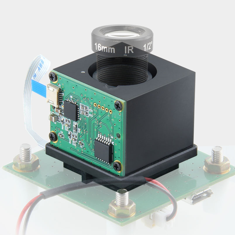
These include the complete controller for the used Piezo actuator.
The focus position can easily be changed by simple  ASCII command sent over USB or UART or I2C.
The repeatability here is +/- 3um for the standard type an +/- 0.5um for the precision type.

With such modules you could take a series of images in different image distances and therefore different Object distances.

One application could be Iris detection , taking an image series with a free running highspeed camera , for example with 300fps – every 2cm from 500-1000mm, then choose image from the series that has the best sharpness.
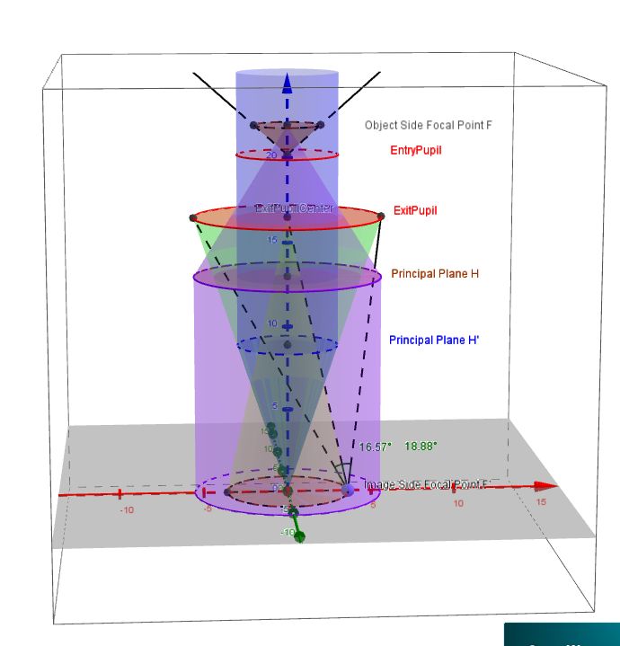
What’s the relationship between the main features of a lens?

We describe here the (yes, complicated) relationships between :

Using a drawing :MainLensFeatures

Given : focal length, F#, Image circle, CRA
Lets assume the object is at infinity because only there, the F# is defined and the image shall be focussed).

  1. Determination of the Entrance Pupil Diameter (EPD)
    The F# is the ratio :   focal length / EPD
    So EPD = focal length / F#.
    All light arriving parallel to the optical axis in a cylinder with this diameter enters the lens and is focussed to “somewhere” on the optical axis.
  2. Determination of the image side Principal plane H’
    Per definition, the focal length is the distance of the image side principal plane to the image of an on-axis object point at infinity position.
    This image is called Focal point. As the image is focussed, the focal point is located where the optical axis intersects the sensor.
    In Practice, this is not necessary the center of the sensor! The sensor might be shifted!
  3. Determination of the angle under which light arrives in the focal point.
    The distance of the image side principal plane H’ and the sensor is the focal length.
    We also have the EPD.
    From this we can calculate the sine “NA” of half the angle in the focal point as
    NA = 1/ 2F#
    So arcsin NA is half the angle and   2 arcsin NA is the full angle.
  4. Determination of the Exit Pupil Center “XPC”
    Fomr the Chief Ray angle and the image circle we can find the intersection point where the rays arriving at the image circle rim under the angle CRA.
    We call this point exit pupil center EPC.
  5. Determination of the Exit Pupil and the Exit Pupil Diameter (“XPD”)
    The F# determined the image side NA. we get the exit pupil as intersection of the resulting cone in the distance of the XPC.
  6. Determination of the shallowest and steepest angles under which light arrives at an image point P
    P, together with the optical axis defines a plane.
    The intersection of this plane with the exit pupil defines a segment where it intersects with the exit pupil. The min / max of the off axis angle (absolute value) of the left and the right segment end points to Pdefine the min and max Angle at which light arrives at P.
  7. Determination of the object side focal point
    With the XPD we get an on-axis cylinder of the diameter XPD.
    Light arriving from Infinity parallel to the optical axuis inside this cylinder is focussed in the object side focal point F.
  8. Determination of the Object side Principal plane H
    the principal plane H is by definition perpendicular to the optical axis through a point that is “focal length” away from the object side focal point.
  9. Determination of the “Object Circle”
    If light from various directions arrives from the image side direction exit pupil, then at a plane perpendiculat trough the Object side focal point theres a disk of light we for now call “object circle”.
  10. Determination of the entrance pupil center
    Half the object side viewing angle is the object side chief ray angle
    Where the rays through the rim of the object circle arriving at the Object side chief ray angle meet is the Entrance Pupil Center. “EPC”.
  11. Determination of the Entrance Pupil
    From entrance pupil position and diameter we have the Entrance Pupil.
    All object side ray that are in the field of view and go through the entrance pupil have an image in the image circle.