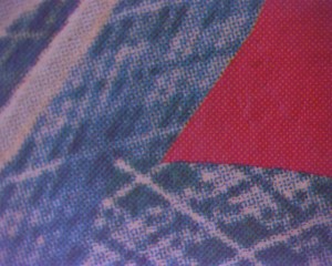
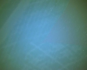
Sometimes the contrast of the image heavily drops, when we use coax types of telecentric lenses:
Let’s take a look at the situation, when we use the coax type of telecentric lenses.
Image with deactivated coax illumination (and auto exposure):
Image with activated coax illumination
Question: What’s wrong with the lens or illumination?
Answer: The lens and illumination are just fine, but the object has been chosen wrongly.
The most likely reason for this symptom of dropping contrast is neither the lens nor the illumination, but the object (!).
Let’s have a look at the so-called “beam splitter cube” used in most coax type telecentric lenses:
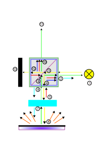
The (idealized) principle is like this:
- From a light source (1) light enters a glass cube whose diagonal (3) is semi-transparent. 50% of the light passes through).
- 50% of the light is absorbed in a “light trap” (13),
- The other 50% is reflected by the object and enters the glass cube again
- 50% of this light (=25% of the initial light) is reflected back to the illumination
- The other 50% of this light (=25% of the initial light) finally reaches the camera at (11)
So what’s the reason for the bad image contrast?
Of course the stray light doesn’t increase .. ; the “useful information” is just reduced.
This results in an image with low contrast.
To show this in detail, let’s follow the light through the beam splitter cube:We assume here an AR coating of the cube and lenses of 99% and 10% absorption by the mirror.
- From (1), the light reaches the surface (2) of the beam splitter cube
- The cube is made of glass. Uncoated glass typically reflects 4% of the incoming light. If the glass has an anti-reflection coating, it reflects less light. For example 1%, with only 99% entering the cube.
- The light reaches the diagonal of the cube, where the light is actually “split”. This can be achieved with a dielectrical coating (causing some polarization) or with a thin aluminum coating.
- This coating usually absorbs light, for example 10% with an aluminum coating. So only 89% of the light is split.
- Half of the 89% (=44.5%) is transmitted towards the light trap,
- The other 44.5% is reflected towards the object.
Let’s follow the light towards the light trap first:
- Just before leaving the beamsplitter cube, 1% of this light is reflected (at (12)) back to the 50:50 mirror (3)! This 1% is 0.445% of the original amount of light. This doesn’t sound much, but read on.
- At the mirror (3) 10% of the light is absorbed again, 0.4005% is split 50:50
- Therefore 0.2% is transmitted to the illumination, but another 0.2% is reflected towards the sensor.
- at (10) 1% of 0.2% is reflected, which is small enough to ignore it.
Now let’s trace the other part of the beam
- Just before leaving the beamsplitter cube, 1% of this light is reflected (at (12)) back to the 50:50 mirror (3)! This 1% is 0.445% of the original amount of light. This doesn’t sound much, but read on.
- At the mirror (3) 10% of the light is absorbed again, 0.4005% is split 50:50
- Therefore 0.2% is reflected to the illumination, but another 0.2% is transmitted towards the sensor
- at (10) 1% of 0.2% is reflected, which is small enough to ignore it.
We left the beamsplitter towards the object, so is that it? Unfortionately not!
- Usually the beamsplitter is not the last element in the lens. Let’s assume there is one last lens element, and let’s say it’s an achromat (displayed here as a rectangle, that was easier to draw! )
- At the first surface of this lens element (5) 1% of the light is reflected (roughly another 0.4% of the original amount) back to the beam splitter cube and 99% of it reaches the mirror surface.
- The mirror (9) absorbs 10% of this. 50% of the remaining light roughly 0.18%) is transmitted towards the camera
- The other 50% is reflected back to the illumination.
- Similarly, on the other side of the lens 1% of the light is also reflected .. Another 0.4% (approximately) travels towards the cube and another 0.18% travels in the direction of the camera.
Finally the light reaches the object. So is everything good now ? Not at all !
- If the object is a mirror, it still absorbs light anyway!
(for example 10% for aluminium-on-glass mirror, 2% for silver on glass, 30% for chrome on glass) - Let’s say we have an aluminum mirror and (only) 10% of 44% is absorbed. Then 39.6% of the light travels back towards the cube.
- 1% of this is reflected at the front lens, another 1% at the reverse side of the front lens
- A further 1% is reflected at the cube surface and approximately 38.4% reaches the mirror
- The mirror absorbs 10% of this and the remaining 34.5% of light is split 50:50
- 50% passes the mirror (17.25% of the original amount) and travels towards the camera. 1% of which is reflected at the cube surface, but we can ignore this, as its influence is small.
- So instead of the “ideal” 25% only 17.25% of the light arrives at the camera, overlaid by 0.2+0.2+0.36% = 0.76% from internal reflections.
- 0.76% is a bit over 4.4% of the useful image information , so a bit of the contrast dies.
But that’s still aceptable!. Remember, in the above photos, the object wasn’t a mirror but diffuse reflecting paper. What happens in this case? .. Prepare yourselves!
- When the object is diffuse, like paper, 44% of the input light reaches the object.
From whichever direction you look, the lightspot can be clearly seen! - This means however that the 44% is spread over 360 degrees horizonally and nearly 180 degrees vertically.
- Let’s assume only light from, 10 of the 180 degrees is reflected back to the lens.
Let’s imagine that we have a hemisphere-shaped cake, and we cut it in 18 looong pieces like pages of a half-opened book. Each piece corresponds to 10/180 degrees of a hemisphere.
Now we keep the cake on the table and turn it by 90 degrees and cut 18 slices again like we did before. We learn an angle of 10 degrees in x and y corresponds to 1/(18*18) of the full cake, surface, i.e. only (1/18*18) = 0.3% of 44% (= 44%*0.003=0.1% ) - So only 0.1% of the original amount of light travels towards the lens, 1% of which is reflected at each side of the lens another 1% at the cube surface,
We ignore absorption by the object here, which could be a big factor. - 97% of this 0.1% reaches the mirror, which absorbs 10% (so we have 87%)
- 50% of this (=43.5% of 0.1% = 0.04%) is transmitted to the camera
- So 0.04% of “useful” information from the object is overlaid with 3.3% of internal reflections!
- This means that the “stray light” of the internal reflections is 0.76%%/0.04% = 0.0076/0.0004 = 19 times stronger than the “useful” light.


