Archives

Abbe-Method

Measuring method (named after Ernst Abbe) used to determine the focal length and the position of the principal planes of a lens singlet or a lens system (=objective) on the optical axis.

How to determine the focal length:
The position of the lens is fixed and the camera (or the screen ) is moved depending on the object position, that you get a focused image (in the image center). Different object positions result in different camera- or screen distances
FocalLength = {\frac  {DifferenceOfObjectpositions}{{\frac  {ObjectSize}{ImageSize2}}-{\frac  {ObjectSize}{ImageSize1}}}}

How to determine the focal length of an objective (= (= lens system)):
The Position of a lens (and the lens singlets in it) are fixed and an arbitrary Point O on the optical axis is marked as reference point, for example the center of the lens or the center of the first lens element).
Now we measure the distance x from the reference point to the object, the distance x’ to the image and the image size B.
You get a list of Magnifications
\gamma = \frac {ImageSize}{ObjectSize} = \frac{B}{G},
and equations from refererence Point to object
x=f\left(1+{\frac  {1}{\gamma }}\right)+h
and reference point to image:
x'=f'\left(1+\gamma \right)+h'
Where h und h’ are the distances from object side resp. image side principal planw to the reference point.
Aperture angle

Angle that the lens can see in the direction of a given sensor measure.

The angles in horizontal, diagonal and vertical directions differ.
Please distinguish between the max. possible aperture angle and the actual aperture angle.
Actual aperture angles are influenced by the length of used extension rings,and even focus distances (because they are mostly achieved by simulating extension rings) max possible aperture angles aren’t
Changing the sensor size changes the actual aperture angle, max possible aperture angles aren’t
Datasheets of lenses usually show aperture angles for a given sensor size! Changing the sensor size changes the angles!
For lenses without distortion a lens that has the diagonal of the sensor as focal length has 53.1 degrees
A (no distortion) 6mm lens on a 1/3″ sensor,a 8mm lens on a 1/2″ sensor and a 16mm lens on a 1″ sensor have the same diagonal aperture angle of 53.1 degrees

Blue Shift of Bandpass Filters

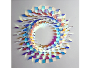
Here’s a wonderful example of Art based on dichroic filters.

Image "Irdien" by Cris Wood www.chriswoodglass.co.uk

Art based on “dichroic filters”:  “Irdien” by Chris Wood
www.chriswoodglass.co.uk          with kind permission of the artist

We notice that the colors change at different angles of the filters.

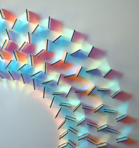
Even more visible here :

http://www.thisiscolossal.com/wp-content/uploads/2014/09/glass-5.jpg

Art based on Dichroic filters : Photo used with kind permission of the Artist: Chris Wood, www.chriswoodglass.co.uk

We notice especially that for filters of the outer circle, filters that  have a 90 degree different orientation have about the same color transmission. Especially look at the topmost, the rightmost (both orange colored) and the top-right-most filter (with a purple touch)

Below is a calculator that gives an idea about the resulting interval of wavelengths (called “band” ) when you use the filter at some angle off the designed incident angle.

The filters above seemed designed for an incident of 45 degrees to the surface. Thus +45 and -45 degrees result in the same color and in between we get a blue shift of the wavelength that pass.

The calculation is just for the primitive case of a rectangular transmission curve.

Bokeh

Bokeh is a word that describes blurry, quite large, often round blobs in the image, often as background of some focussed image part.

As an example see the Bokeh of these lights of a Christmas tree.

Image of a Christmas tree showing Bokeh

Bokeh

“Bokeh” actually is the image of typically point sized Objects in a distance far outside the DOF, most often point size objects at infinity while the lens is focussed on some near distance or point sized object in the foreground when the lens is focussed on infinity.

A diagram explains this best :

The lowest large dot on the right is an example for Bokeh.

The shape of the Bokeh is the shape of the physical Iris. This is why many customers prefer round iris shapes
Bokeh of a catadioptric lens (=mirror lens), (C) Wikipedia

Bokeh of a catadioptric lens (=mirror lens), (C) Wikipedia

The Bokeh has ring shape here, because the image was taken with by a mirror lens, so that the iris center wasn’t exposed to light.

focal length

The focal length is the distance from the Image side principal plane to the image of objects at infinity.

For single lenses in air that is equal to the distance from the first focal point to the first principal point.
(in each case measured from the left to the right)

Note that this is a positive value for converging lenses and a negative value for the divergent lenses.

The larger the focal length, the smaller the aperture angle of the lens and the smaller the object section that is displayed full-frame on the sensor.
The lens captures less of the object. Extremea are telephoto lenses and finally telescopes.

The smaller the focal length, the larger the aperture angle of the lens and the larger the object section which is displayed full-frame on the sensor.
The lens captures more of the object. Extreme forms are fisheye lenses.

Lenses are typically listed, sorted by focal length. As an approximation, lenses with larger focal length see a smaller portion of the object (in more detail).

There are exceptions! (See: pseudo-knowledge: viewing angle and focal length are equivalent)


The following calculators determine focal lengths. They assume, a pin hole lens model, the Chief Ray Angles are assumed to be the same on object and image side.
Therefore for wide angles a too small focal length is returned .. (as all focal length calculators on the internet do 😉 );

Also keep in mind that the Gauss lens equation and the Newtonian image equation both assume same CRA on object and image side, which is nearly never given for wide angle lenses and for sure not for fisheye lenses.

Therefore when you calculate focal length, object and image distances, they will in general differ from the real world situation you measure!


The following calculator determines focal length from angles.
However, Viewing angles change with the working distance! Also, a Pinhole lens model is assumed. Thus for wide angles a too small focal length is returned .. (as all focal length calculators on the internet do 😉 )

For the next calculator it is very important to correct the distortions before doing the calculation:

IR corrected

When lenses are designed, one of the important parameters is the spectrum for which the lenses are to be used.
Most lenses on the market are “corrected” (read : “designed”) for the visible range of the light, the part that humans can see. These are wavelengths between about 420nm and 720nm, deep violett to deep red colors.

Lenses are called IR corrected, if they are designed for near Infrared light (NIR .. roughly 800 to 1100nm), so you _could_ use them if your Illumination contains these wavelengths.

If lenses are not IR corrected, they will typically have a so called Focus Shift (or “longitudinal color aberration”) , say the focal length of an IR image is different from the focal length of the color image, thus either the color image or the IR image is focussed, but in general not both.

Lenses that _are_ IR corrected usually have a special antireflection coating , suited for the infrared spectrum.

One thing you have to take into account however is the quantumefficiency of your sensor, say, how well it can receive NIR light. Often sensor can receive light in this range of wavelengths one one third as good as they do for the visible range, say the brightness of the image is just 1/3 .. and lower. Ask your supplier about sensors dedicated for IR light.

If a lens is designed for VIS (= visible light) and also for NIR, you have to keep in mind that you in general can NOT get a nice color image _and_ a nice NIR image at the same time.

This is because color pixels let various NIR wavelengths pass say, the nice color images are overlayed with IR light.

According to the Rayleigh criterionlight of, say, 850nm wavelength can achieve only half the resolution of a lens optized for half the wavelength (425nm)
This means, even a cristal clear color image is overlayed by a slightly blurred IR image.

Say, if you _can_ choose, go for Visible light, not for NIR light.

If you need IR light AND Visible light at the same time, for example door cameras have this challenge, then go for a special filter that lets VIS pass plus a small IR range, for example 940 +/- 20nm

Koehler-Illumination

Illumination principle used to convert an inhomogene illumination to a homogene Illumination without too much light loss

The main components of a Koehler-Illumination are the “condensor” that maps the illumination (for example some LEDs) to the location of the second component, an Iris, often a manual Iris.
The “Collimator” maps the Iris (and therefore the images of the LEDs) to infinity. So the light will leave the collimation parallel.
Because the LEDs have a certain non-zero diameter, so have it’s image at the Iris. As the result the light from each arbitrary small point leaves the collimatior parallel, but at an Angle.
The sine of this off axis angle is called numerical aperture “NA” (in air) .
The speciality of the Koehler Illumination is, that the light of all these parallel light beams meets at (ideally) one position, markered as “best mix” in the graphics. For best results the real world object to be illuminated shall be at this best mix point.

magnification

a) For telecentric lenses this is
 the ratio of image size to object size
b) For entocentric lenses this is
 the ratio of image size to object size at a given distance.

Example (telecentric lens)
If you want to map an obbject of 10mm diameter to s Sensor with 1/3″ (= 6mm diagonal!), you need a magnification of 6/10 = 0.6x
The lower the magnification, the larger the visible object section. Say, if you can’t get a lens with the desired magnification, you can choose a lens with a slightly smaller magnification, eg 0.55x instead of 0.6x in the above example.
Example (entocentric lens)
With a 1/2 “Sensor (8mm diagonal), a distance of 500mm and an object cutout of 16mm diagonal, 
 the magnification is  8/16 = 0.5.
Doubling the distance (to 1000mm) allows the lens to see about twice as much (32mm ). As a result, a magnification of 8/32 = 0:25 results.
In particular, the magnification at infinity is zero!
Since for entocentric lenses the FOV changes with the working distance, the magnification changes too!
Each entocentric lens achieves each magnification (if it can be used beyond the MOD)! .. We just have to choose the right distance between the object and the camera.
So there’s the naive hope that just one entocentric lens could be enough for all applications then …
The Problem is however, that (for entocentric lenses) with the distance to the object, also the perspective changes. Telecentric lenses keep the perspective!
Magnification  = \frac{ImageDistance}{ObjectDistance}= \frac{ObjectNA}{ImageNA} = \frac{SensorSize}{ObjectSize}
Typical high magnifications in image processing end at 10x.
Typical high magnifications in microscope imaging end at 100x, where magnifications above 40x usually need immersion, say, the lens is used in oil!.
When you read about higher magnifications like 200x and higher, there’s an excellent chance that the size of the monitor is also included!

see :
optical magnification
electronic magnification
monitor magnification