Archives

S-Mount

(= Short Mount) 
 is a lens mount for use of mini-lenses with M12x0.5 thread (diameter = 12mm, 1 revolution = 0.5mm stroke. 


S-mount lenses are either used in special holders, or with adapters or in C-mount CS-mount cameras.

Note:
Like with C-mount, CS-mount and F-mount lenses diameter and thread pitch are fixed.
But different from these the back flange length (distance from the mechanical stop of the lens to the sensor) is NOT standardized.
This can lead to mechanical problems with filters mounted between the lens and sensor.

Scheimpflug principle

Normally, the focus plane is 90 degree to the optical axis. This is due to symmetry reasons.
A problem arises when two objects have so different distances, that they can not be focussed at the same time.

Different_Object_Distances

Theodor Scheimpflug had a genius idea : lets tilt the camera!

scheimpflugs_idea

Then all point in the A-B-plane will be focussed!

Just tilting the camera of course is not enough, to get a focussed image. The Gaussian focus equation also must be satisfied.
The Gauss equation is however equivalent to the second Scheimpflug priciple.

First Scheimpflug principle:

Three planes must share a common line:

  • The tilted plane containing the desired objects
  • The sensor plane
  • A plane perpendicular to the optical axis of the lens.

For a theoretical “thin lens” (=of virtual length 0) , it’s clear where this plane is. For the exact location in a real world lens, see below.

For a mind game lets keep the sensor plane and the object plane fixed and non-parallel. This defines a shared common line in 3D space. Through each line in Space there is an infinite number of Planes, containing it.
Obviously not all can be the plane of best focus.
Say:

The first Scheimpflug principle is just a necessary condition, but not a sufficient condition to get a focussed image of a tilted object plane on the sensor.

In general the lens is tilted, but the image not focussed.
However, as soon as wwe use the lens focus mechanism, the first Scheimpflug principle is not satisfied any more, we would have to tilt the lens a little to satisfy the first criterion, but then the image is not focussed any more, etc.

The second (sufficient) condition can be the

Gauss focus equation:

\frac{1}{focal length} = \frac{1}{object distance} + \frac{1}{image distance}

But instead of the Gauss focus equation we can use the

Second Scheimpflug principle:

These three planes must share a common line:

  • The tilted plane containing the desired objects
  • A plane through the lens center, parallel to the sensor plane
  • A plane perpendicular to the optical axis of the lens shifted by the focal length.

Situations & Applications where to use the Scheimpflug principle:

  • Objects to be focussed have a various vertical distances from the camera (a poster at the wall, the facade of a building with the camera viewing upwards or a document on a table distant from the camera
  • The camera can not be mounted where it should be (because for example to stay out of the way of a robot)
  • The cameras looks at an angle to a more or less flat object
  • Cameras for autonomous vehicles taht have to follow lines or signs on the floor
  • Whenever the desired plane of focus is not parallel to the camera sensor
  • Laser-Triangulation
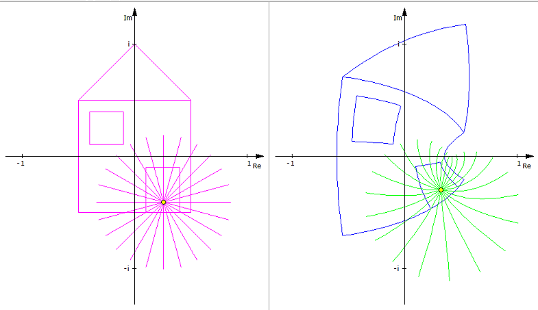
The following interactive drawing is just for illustration purposes!

Usage: First place the object center (the green dot, the spot where the optical axis meets the object) at a local you like , for example at 60 on the x-axis.
Them move the lens (the other green dot) to a location where it’s possible to place the camera-lens position.
The interactive graphic keeps the optical axis in the center of the lens and maps the edges of the sensor to the wanted object plane.
The magnification if measured perpendicular(!) to the optical axis.
Keep in mind, that on your monitor you’ll see a trapezoid / trapezium)
Sensor-Format

Sensors of different shapes and sizes are used in image processing and surveillance technology.

On one hand the sensors have a different ratio of width to height,
for example z.B. 1:1, 4:3, 16:9, 16:10

On the other hand, the sensor size differs, that is described by the sensor diagonal


[table]Sensor format, length of diagonal
1/4″, 4.3-4.5mm
1/3″, 6mm
1/2.5″,7.13mm
1/2″,8mm
1/1.8″,8.9mm
2/3″,11mm
1″,16mm
4/3″,22.5mm
[/table]

sign conventions

In order to achieve similar optical formulas across various authors, an agreement on some sign convention is necessary:

sign_conventions

The z-axis of a system is the optical axis.
As usual we assume thet the light passes from left to right through the lens elements.
Initially the light travels from -z to +z

The y-Axis is perpendicular to the z-axis and in the plane of the monitor/papersteht
The x-Axis is perpendicular on the z-axis and the y-axis and is drected into the screen/paper.

The first optical surface then has the radius R1 and the second optical surface has the Radius R2, where infinit values signal plano surfaces (blue colors in the graphic).

If the light first meets the optical surface and then the center of curvature then the radius has a positive sign, (green color arcselse a negative sign (red color arcs).

R_a above is positive and R_b is negative.

Angles are measures between the optical axis and the beam, where the smaller of the two intersection angles is used.
Incident angles are measured between the surface normal and the incident beam.

signs of refraction indices are negated after a reflection.

[table caption=”sign conventions” width=”500″ colwidth=”40|20|100″ colalign=”left|center|left”]
measure,sign,explanation
object distance,+,object is left of the refracting surface
object distance,-,object is right of the refracting surface
image distance,+,image point is right of the refracting surface
image distance,-,image point is left of the refracting surface
radius of curvature,+,center is right of the refracting surface
radius of curvature,-,center is left of the refracting surface
focal length (object side), +, left of the lens
focal length (image side), -, right of the lens
object distance from focal point F,-,left of object side focal point
image distance from focal point F’,+,right of image side focal point
object height,+,above optical axis
object height,-,below optical axis
angle,+,measured counterclockwise
angle,-,measured clockwise
[/table]

stereographic

stereographic lenses are a class of fisheye lenses

sterographic lenses are also called “ conform“or “ winkeltreu
stereographic lenses use image mapping functions of type
r = 2 f tan \frac{\theta}{2}

maintains angles

[table caption=”stereographic angles” width=”500″ colwidth=”50|50|50|50″ colalign=”center|center|center|center”]
weak,medium,strong,max
94,131,180,<360
[/table]

Example of a Stereographic image :
stereographic

see Fisheye Types