Standardized interface for the mounting of lenses, described in ISO 10935 (1996-12) Optics and optical instruments – Microscopes – Interface Type C
Standard interface for mounting of lenses.
The diameter of the thread is 1 “(one inch) and there are 32 threads to 1” in length.
The distance between the mechanical stop of the lens and the sensor in air is 17,526 mm
This is about 5mm more than for CS-mount lenses. C-mount lenses can be used with a 5mm extension ring (“C- to CS-mount adapter”) with CS-mount cameras.
CS-mount lenses however can not be used with C-mount cameras.
C-mount lenses are usually used for factory automation lenses.
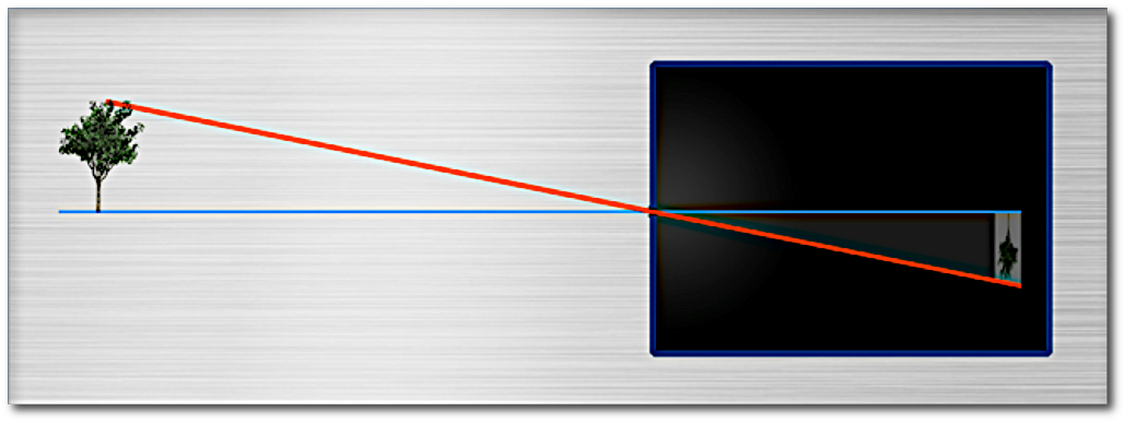
The principle of the camera obscura (= pinhole camera) is like this:
The disadvantage is clearly, that the image on the image plane is very dark. The needed exposure times to take an image can well be minutes!
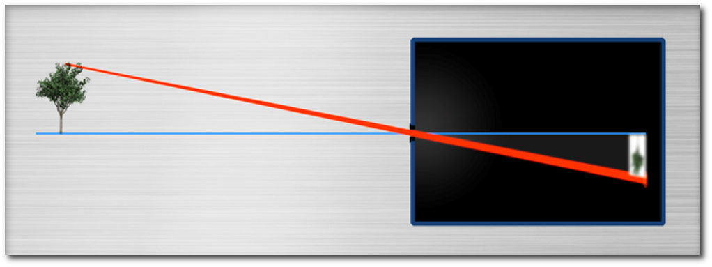
Idea: Lets use a larger hole :
Now, however, the image not only gets brighter (as intended) but also gets blurry, because the light not only passes through the center of the hole. So not only the correct position of the image is exposed to the light, but also the direct neighbours.
As a result, the image of an object point is not just a point, but instead a little disk, the so called “Circle of Confusion” (CoC).
For long distant Objects the diameter of the CoC equal the diameter of the hole!
From an object point light rays spread cone shaped in the direction to the rim of the entrance Pupil and later from the direction of the rim of the exit pupil to the image point.
The chief ray is the axis of those cones and contains the center of the Entrance Pupil and the center of the mechanical iris.
See Chief Ray Angle
Images of point size Objects would ideally be points. For physical reasons (“diffraction”), we only obtain little disks of light.
The so called circle of confusion (also called “Airy disk”) is the smallest disk of light, that an ideal lens can theoretically generate on image side.
The smallest possible diameter of a circular disk that a “perfect” (=diffration limited) lens can generate on image side is given by the Rayleigh Criterion.

Diffraction at pixel Level
The optical term “contrast” of an image is pretty much what we would expect from our daily use of the word.

However, we have to distinguish global contrast …

… from local contrast :

The global contrast in the two images above is about the same, however the local contrast (the change from pixel to pixel) is less high in the lower image, because of the slight blurring.
The local contrast is described by the MTF-curve.
Contrast can be a difference in brightness but also a difference in color
Contrast heavily depends on environmental
light. Switch off the
light at night and all contrast is gone!
Contrast can be increased or reduced by changing the
light situation.
Red writing on a white paper becomes invisible under red
light. Both paper and writing look red, the contrast is gone.
Yellow Writing on a white paper is nearly invisible on the image of a monochrome camera. Illumination with blue
light increases the contrast nicely.
Angle between the (usually image side Chief Ray and the optical axis
Standardized interface for the mounting of lenses, described in ISO 10935 (1996-12) Optics and optical instruments – Microscopes – Interface Type CS
The diameter of the thread is 1 “(one inch) and there are 32 threads to 1” in length.
The distance between the mechanical stop of the lens and the sensor in cross bolts in air is 12.52 mm. These are about 5mm less than for C-mount lenses.
C-mount lenses can (with an 5mm extension (C-CS-mount adapter)) be used in CS-mount cameras,
However CS mount lenses can not be used in C-mount cameras.
CS-Mount lenses are mostly used in security systems, often these are wide-angle lenses.