See also:
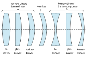
How to tell whether a lens singlet is converging or diverging?
Light that we can see (“visible light”, “VIS”) is a small part of a spectrum of a thing called “electromagnetic radiation”, distinguished by something we call “wavelength”.
As the wavelength varies in the visible spectrum, the light appearantly changes color from violet to red.

There are no actual boundaries between one range of wavelengths and another. So numbers associated with a certain range are only approximate.
If we explore the spectrum from long wavelengths to shorter wavelengths, we meet :
Rings of M12x0.5 female thread to fix s-mount lenses using the principle of the counter nut.
Lock-Rings are available from stock at www.lensation.de
a) For telecentric lenses this is
the ratio of image size to object size
b) For entocentric lenses this is
the ratio of image size to object size at a given distance.

see :
optical magnification
electronic magnification
monitor magnification
see Magnification
Mechanical obstacles in the path of light cause a drop in brightness (“artificial vignetting”).
A drop in brightness can also happen unintentionally (and thus may be a design mistake). You can correct it usually by stopping down the lens (smaller the iris opening) by for example 2-3 f-stops)
Looking from the front to a lens has a certain resemblance to axially look into a cylindrical tube.
At the other end of the tube can be seen a circle, namely, the end of the tube.
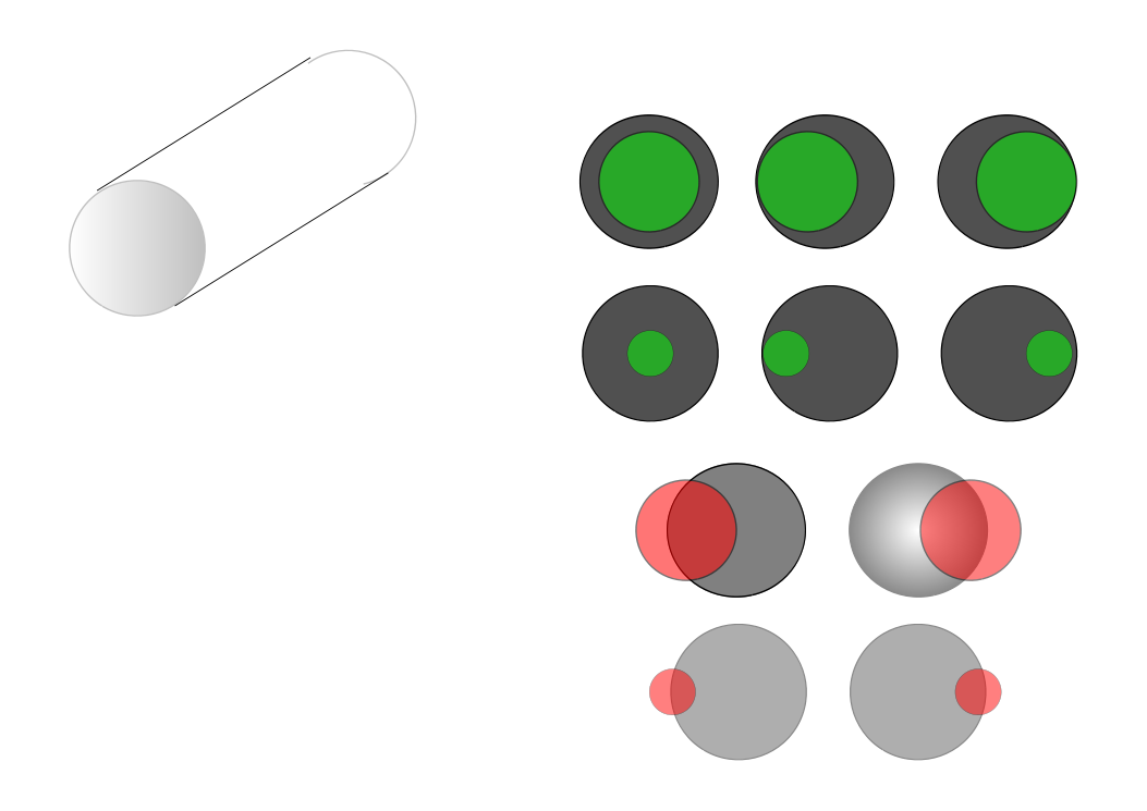
The small green or red circle above suggests doing a stopped-down lens (= lens with a large aperture number).
Tilting the tube (lens) slightly off-center, for some degree a complete circle remains visible ( marked green in the drawing above).
We see, that for small circles (= large f-numbers) the tube (=lens) can be tilted more before the full circle touches the edge of the cylinder.
When we tilt the tube (=lens) (lens) more, the complete circle is no longer visible,, marked in red.
That fact that the complete circle is visible is a sign that in this direction the entire light can pass through the tube.
The full circle turns into a “biangle” (= intersection of two circles).
This is a sign that in this direction not all of the light can pass the cylinder (=the lens). Vignetting occurs.
The percentage of light passing is
100 * (area of the biangle / area of the circle
When we connect the image points of a sensor and the corresponding object points, This line has an angular displacement from the optical axis. The angle corresponds to the deflection of the cylinder above.
Mechanical vignetting occurs symmetrically and therefore first occurs in the corners of the sensor.
When we tilt the tube (=lens) too much, no light passes.
The area on the sensor receiving light is round (due to circular symmetry reasons) and is called “image circle”.
Black areas are usually to be avoided in the image, say, the image circle got to be larger than the sensor diagonal.
See also “sensor size”
see tangential plane
= Minimum object distance
Closest distance for which the lens works optimal and especially can be focused.
This does not mean that a lens at shorter working distances no longer “works”. … just: please do not expect the “perfect” picture quality.
Focus on shorter working distances can be achieved by increasing the distance between sensor and lens (= screw type design of the lens and possible use of distance rings)
When working at shorter distances than MOD generally expect:
describes, how much larger an object is displayed on a monitor than it is in real life.


Then

and

Because

we get :

see: rad
