The sagittal plane through a point is a plane perpendicular to the tangential plane trough the point, containing the point and the center of the entrance pupile.
Perpendicaular to it is the tangential plane.
The sagittal plane through a point is a plane perpendicular to the tangential plane trough the point, containing the point and the center of the entrance pupile.
Perpendicaular to it is the tangential plane.
Normally, the focus plane is 90 degree to the optical axis. This is due to symmetry reasons.
A problem arises when two objects have so different distances, that they can not be focussed at the same time.

Theodor Scheimpflug had a genius idea : lets tilt the camera!

Then all point in the A-B-plane will be focussed!
Just tilting the camera of course is not enough, to get a focussed image. The Gaussian focus equation also must be satisfied.
The Gauss equation is however equivalent to the second Scheimpflug priciple.
Three planes must share a common line:
For a theoretical “thin lens” (=of virtual length 0) , it’s clear where this plane is. For the exact location in a real world lens, see below.
For a mind game lets keep the sensor plane and the object plane fixed and non-parallel. This defines a shared common line in 3D space. Through each line in Space there is an infinite number of Planes, containing it.
Obviously not all can be the plane of best focus.
Say:
In general the lens is tilted, but the image not focussed.
However, as soon as wwe use the lens focus mechanism, the first Scheimpflug principle is not satisfied any more, we would have to tilt the lens a little to satisfy the first criterion, but then the image is not focussed any more, etc.
The second (sufficient) condition can be the

But instead of the Gauss focus equation we can use the
These three planes must share a common line:
Usage: First place the object center (the green dot, the spot where the optical axis meets the object) at a local you like , for example at 60 on the x-axis.
Them move the lens (the other green dot) to a location where it’s possible to place the camera-lens position.
The interactive graphic keeps the optical axis in the center of the lens and maps the edges of the sensor to the wanted object plane.
The magnification if measured perpendicular(!) to the optical axis.
Keep in mind, that on your monitor you’ll see a trapezoid / trapezium)
Sensors of different shapes and sizes are used in image processing and surveillance technology.
On one hand the sensors have a different ratio of width to height,
for example z.B. 1:1, 4:3, 16:9, 16:10
On the other hand, the sensor size differs, which is described by the sensor diagonal:
For sensors >= 1/2″ , the diagonal is 16mm * inch
for example 16mm * 1/2 = 8mm
For sensors < 1/2" , the diagonal is 18mm * inch
for example 18mm * 1/3 = 6mm
See: vidicon tube
In order to achieve similar optical formulas across various authors, an agreement on some sign convention is necessary:

The z-axis of a system is the optical axis.
As usual we assume thet the light passes from left to right through the lens elements.
Initially the light travels from -z to +z
The y-Axis is perpendicular to the z-axis and in the plane of the monitor/papersteht
The x-Axis is perpendicular on the z-axis and the y-axis and is drected into the screen/paper.
The first optical surface then has the radius R1 and the second optical surface has the Radius R2, where infinit values signal plano surfaces (blue colors in the graphic).
If the light first meets the optical surface and then the center of curvature then the radius has a positive sign, (green color arcselse a negative sign (red color arcs).
R_a above is positive and R_b is negative.
Angles are measures between the optical axis and the beam, where the smaller of the two intersection angles is used.
Incident angles are measured between the surface normal and the incident beam.
signs of refraction indices are negated after a reflection.
[table caption=”sign conventions” width=”500″ colwidth=”40|20|100″ colalign=”left|center|left”]
measure,sign,explanation
object distance,+,object is left of the refracting surface
object distance,-,object is right of the refracting surface
image distance,+,image point is right of the refracting surface
image distance,-,image point is left of the refracting surface
radius of curvature,+,center is right of the refracting surface
radius of curvature,-,center is left of the refracting surface
focal length (object side), +, left of the lens
focal length (image side), -, right of the lens
object distance from focal point F,-,left of object side focal point
image distance from focal point F’,+,right of image side focal point
object height,+,above optical axis
object height,-,below optical axis
angle,+,measured counterclockwise
angle,-,measured clockwise
[/table]
stereographic lenses are a class of fisheye lenses

maintains angles
| Type : stereographic | weak | medium | strong | max |
|---|---|---|---|---|
| angles | 94° | 131° | 180° | < 360° |
Example of a Stereographic image :
see Fisheye Types
A tangential (also called meridional) plane in 3D is in general a plane containing the optical axis.
The tangential plane through a point is the plane in 3D that contains the point and the optical axis.
The tangential ray trough a point in 3D is the ray in the tangential plane through the point, headed to the centre of the entrance pupil.
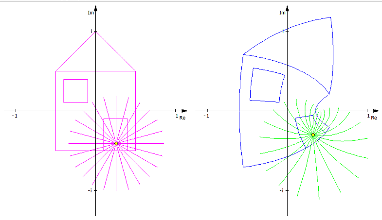
In the following interactive graphics you can move the green point (click to change directions from x-y to z). The rays leave the point direction entrance pupille and ‘fill’ it completely.
Perpendicular to it is the sagittal plane.
Entocentrical lens with a focal lengthlarger than the sensor diagonal, for example a f=8mm lens on a 1/3“ Sensor (that has a 6mm sensor diagonal).
When we use the word “tele lens”, it must be perfectly clear, which sensor is involved.
(Depending on the sensor) the same lens can be wide angle lens, tele lens or normal lens.
Total internal reflection (“TIR”) occurs, when the angle of incidence of a ray propagating from a higher indes medium to a lower index medium exceeds the critical angle.

[table caption=”Examples for critcal angles” width=”200″ colwidth=”100|100″ colalign=”left|left”]
 ,
,
1.3, 50.3°
1.4, 45.6°
1.5, 41.8°
1.6, 37.8°
1.7, 36.0°
1.8,33.7°
1.9, 31.8°
2.0, 30.0°
[/table]
for an interactive example, see refraction
Kinds of vignetting to distinguish: