see Petzval Sum
Archives
Petzval Sum
In optical lens design the Petzval sum describes the image curvature of an optical system.
The formula was developed by Josef Maximilian Petzval and published 1843.
For a series of thin lenses holds

or more general

where:
 : radius of the i’th surface,
 : refraction index before the refraction
 : refraction index after the refraction
The displacement of an image point at height  from the paraxial image plane is

The Petzval condition says that the curvature of the Petzval area is zero if the Petzval sum is zero.
If in addition there is no astigmatism, then the image surface is flat.
If there is astigmatism however then the folowing relationship holds between the curvature of the petzval surface and the curvature of saggital and tangential surface

The mean image curvature is here the reciproke mean of tangential and saggital curvature.
Pincushion Distortion

Pincushion Distortion (C) Wikipedia
Pinhole Camera
see camera obscura.
pixel vignetting
A kind of vignetting which occurs exclusively with digital cameras.
Possible causes are:
- the pixels are not completely flat due to construction on the sensor surface, but in small cavities. Too shallow light cast shadows on the edges of the pixels, like the evening sun at some point no longer reaches mountain valleys.
- The sensor uses micro-lenses (small converging lenses) to capture as much light as possible for each pixel. From a certain off axis angle lenses are no longer capable to deflect the light strong enough and the light can’t reach the pixel no more.
- With image side telecentric lenses such vignetting does not occur because the incident light rays are parallel to the optical axis.
The latest sensor technologies however try to correct the Pixelvignettierung on-chip (= directly in the sensor) or by micro lenses that have differently shape in the corners than in the center.
Thus it may happen that the image side telecentric lenses surprisingly show vignetting.
principal plane
Each (rotation symmetric) lens has two principal planes. These (hypothetical) planes are perpendicular to the optical axis and are the planes on which light beams parallel to the axis coming from infinity seem to bend (and then go through the respective focal points).
The image side primary plane is formed where a light ray parallel to the optical axis enters the first lens of a lens system and intersects with the corresponding ray leaving the last lens element.
The object side primary plane is formed where a light ray parallel to the optical axis enters the last lens of a lens system and intersects with the corresponding ray leaving the first lens element.
NOTE:
This only applies to the paraxial optics, i.e. very close to the optical axis.
For rays more distant to the optical axis spherical aberration distorts this behaviour.
This only applies to the paraxial optics, i.e. very close to the optical axis.
For rays more distant to the optical axis spherical aberration distorts this behaviour.
principal point
The intersection of the principal planes with the optical axis.
The two principal points of each (symmetric) lens belong to the Gauss points.
The distance between the principal point and the corresponding focal point is called focal length.
pupil magnification
ratio of the diameter of the exit pupil devided by the diameter of the entrance pupil

For symmetrical lenses, for example a double Gauss design, the pupil magnification is close to 1.
see also:
working F-number
Numerical Aperture
Purple Fringing
Purple colored rim around dark objects, typically on a white background
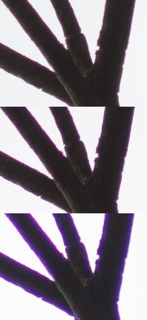
Purple fringing (Image: webfound)
Purple fringing is the visible effect of lateral color-aberrations.
You can imagine this as is one of the Red / Green / Blue Images on a color sensor were a bit too small, for example the blue image. Instead of reaching the white area , together with green and red, it reaches the black area closer to the image center , where no light were expected at all.
That’s why the effect only occurs where (nearly) white and (nearly) black regions meet. If it’s white in a region anyway, it doesn’t matter is all, say, blue) light rays arrive a bit too close to the center, as the “gaps” are filled with other rays. Where black and white areas meet, however, the gaps can’t be filled.
On a monochrome sensor the effect shows as blurry black-white-edges.
The effect is stronger on sensors with smaller pixels, as it’s easier for ray to arrive in the neighbour pixel.
If a blueish ray arrives, say, 2.5um closer to the center than red and green rays, it’s no visible problem for sensors of 6um pixels, as we’re pretty much still in the same pixel. On a sensor with 1.67um pixles we fully reached the neighbor pixel already.
PXT
Synopsys: paraxial trace command