Archives

2 A B C D E F G H I K L M N O P R S T U V W

Laser

What is a Laser?

“Laser” is an acronym for “Light Amplification by Stimulated Emission of Radiation.” Laser light is monochromatic (having only one wavelength) and polarized.

Challenges: Temperature drift can affect the frequency of a laser, as changes in temperature can alter the physical properties of the laser components. Therefore, more expensive lasers have control circuits to ensure frequency stability.

Lasers are monochromatic, but it is still important to keep in mind, for example, in lens design, that the wavelength of cheaper lasers can slightly change with temperature.

The magnitude of these shifts can be around 0.3-0.5 nm per degree Celsius.

As the temperature increases, the power of the laser decreases.

Lens

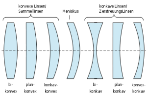
A lens element is a component made of an optical transparent material (usually glass) with two optical active surfaces.
“optical transparent” does not necessarily mean that the component is transparent for human eyes!
For example are lenses made of Germanium not transparent for humans. For certain cameras they are transparent however.
Lenses can be used to focus light
Lens_and_wavefronts[1]
The main effect of lenses is that they map object points to image points.
Let say we have two object points, for example the Top T0 and the bottom B0 of a vase. A two element compound lens works like this :
The object points T0 an B0 are mapped to image points T1 and B1 by lens element number 1. The lens elements are numbered starting from object side.
The images T1 and B1 then become the new “object points” of lens element 2 and map T1 and B1 to “images of image” of T0 and T0, called T2 and B2″.

A lens with 10 lens elements accordingly generates sequences
T0->T1->T2->… -> T10
and
B0->B1->B2->….-> B10

The image produced by a lens can be in front or behind the lens.
It can be smaller or bigger than the object.
Of course we want images of trees to be smaller than trees.
Image of microscopic details we of course want to be larger than the details.

lens equation

The “Gauss lens equation,” as it is known, goes like this:

\frac{1}{f} = \frac{1}{g} + \frac{1}{b}

where
f = focal length,
g = distance to object (measured from object side principal plane H).
b = distance to image (measured from image side principal plane H’).

It can be solved for focal length, object distance and image distance.

We may find the focal length by this equation:

f = \frac {1} {\frac {1} {g} + \frac {1} {b}}= \frac {1}{\frac {g + b}{g \cdot b}}=\frac {g \cdot b}{g + b}

We may find the object distance by this equation:

g = \frac {1} {\frac {1} {f} - \frac {1} {b}}=\frac{f \cdot b}{b - f}

We may find the image distance by this equation:

b = \frac {1} {\frac {1} {f} - \frac {1} {g}} = \frac {f \cdot g}{g - f}

Interpretation of the lens equation

What can be derived from this formula?

  • The focus plane contains the image of infinitely far away objects.
  • When the object moves to infinity (= when g gets infinitely large), then

    \frac {1} {g} \rightarrow 0
    And therefore b = f

  • On the object side, an object with a double focal length distance is mapped to an image with a double focus length distance on the image side.
  • In other words : If we want a 1:1 mapping in distance X from the sensor you have to choose
  • f = \frac {X}{4}

    (but subtract the distance of the principal points from X)

  • The picture is at infinity when the object distance equals the focus length.
  • When an object nears to the focus length, the image distance rises. Therefore \frac {1} {b} \rightarrow 0 holds.
  • For an object closer to the lens than the focal length \frac {1} {DistanceToImage} < 0 holds: the image is generated on the object side (!) of the lens.
  • The object and image distances are calculated from the primary planes on the object and image sides, respectively.
    As a result, the object distance differs from the working distance in most cases.
    The focal length is a paraxial concept. Therefore the Gauss lens equation is only valid in the paraxial region of the lens, the region where sin(x) \approx tan(x) \approx x holds. Most calculators don’t care (including ours), As a result, anytime larger viewing angles are involved, the results are essentially a “informed guess.”


    lensmaker formula

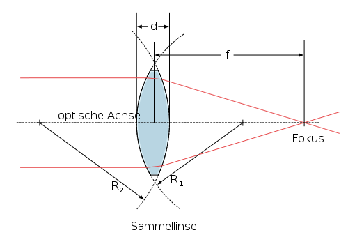
    The formula (at the bottom of this post) shows for thin, spherical lenses the relationship between shape and power.

    Be d center thickness of the lens element.
    R_1 and R_2 be the radii of the spheres that describe the surfaces.
    Keep the sign conventions for radii in mind, however!

    n_0 be the index of refraction of the medium outside the lens and
    n be the index of refraction of the lens material.

    f be the focallength of the lens and
    D be it’s Power, D = \frac{1}{f}

    For spherical optical systems holds generally in the paraxial region:

    D = \frac{1}{f} = \frac{n-n_0}{n_0}\cdot (\frac{1}{R_1} - \frac{1}{R_2} + \frac{(n-n_0)\cdot d}{n \cdot R_1 \cdot R_2})

    Is the surrounding medium air, we get (because n_0 \approx 1) the approximation:

    D = \frac{1}{f} = (n-1) \cdot (\frac{1}{R_1} - \frac{1}{R_2} + \frac{(n-1)\cdot d}{n \cdot R_1 \cdot R_2})

    Are the lenses also thin (idealizing d = 0), the formula simplifies to
    Lensmaker’s formula:
    D = \frac{1}{f} = (n-1)\cdot (\frac{1}{R_1} - \frac{1}{R_2})

    Light

    Light that we can see (“visible light”, “VIS”) is a small part of a spectrum of a thing called “electromagnetic radiation”, distinguished by something we call “wavelength”.
    As the wavelength varies in the visible spectrum, the light appearantly changes color from violet to red.

    image of Frauhofer-Lines

    There are no actual boundaries between one range of wavelengths and another. So numbers associated with a certain range are only approximate.

    If we explore the spectrum from long wavelengths to shorter wavelengths, we meet :

    • “radio waves” : regular broadcast wavelengths are for example 500 meters long, but even longer radio waves exist
    • “short waves” :  (“Radar waves”, “Millimeter waves”)
    • “infrared”
    • “visible light”
    • “ultraviolet light”
    • soft x-rays
    • x-rays
    • hard x-rays
    • gamma rays

    (C) Wikipedia, file : https://upload.wikimedia.org/wikipedia/commons/c/cf/EM_Spectrum_Properties_edit.svg