Help Tutorial Manual
Archives
hypercentric
see “comparison: entocentric – telecentric – pericentric”
hyperfocal distance
When a lens is focussed to the hyperfocal distance H, the DOF of the lens is maximized: The range of acceptable sharpness then extends from  to infinity
There are two Formulas in use:
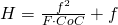
For f=50mm, F2, and CoC = 0.03mm we get

This is the formula we use here. The results just differ in the focal length of the lens.
and

For f=50mm, F2, and CoC = 0.03mm we get

Where CoC is the circle of confusion, F is the F-number and f is the focal length of the lens.
The hyperfocal distance has curious mathematical properties:
The hyperfocal distance H is the distance at which you have to focus an object to receive the largest depth of field. If, namely, a lens is focussed to H, it is focused from to infinity.
When focussed to , so everything from  to
 focused.
When focussed to, so everything from  to focused.
When focussed to, so everything from  to focused.
…
When focussed to , so everything from
 to
 focused.
, so everything from to focused.When focussed to
, so everything from to focused.When focussed to
, so everything from to focused.…
When focussed to
, so everything from to focused.
The distance

is the Depth of field.
Notice:
The depth of field is getting smaller, the larger is n, say the shorter the working distance is!
Image Circle
Although monitors and paper photos are rectangular, lenses are (usually) round.
So why are the images generated by round lenses not round? Well .. images of lenses ARE round.
The diameter of these rounds images is called image or image circle. Outside the image circle the picture (hopefully) is dark. If the image circle is smaller than the diagonal of the sensor, the image has dark corners.
When the Image Circle is smaller than the height of the sensor, the image is round and outside of the image circle it’s dark.
Images of Fisheye lenses are typically like that and are then called “circular fisheye image”. Such image are especially helpful for checking whether the axis of sensor and lens are aligned:
The image circle must be in the middle of the (rectangular) screen image.
Maximum (diameter of the) circle that receives (good quality) image information.
The image circle limits the maximum sensor size for which a lens can be used.
An image circle of 6mm limits the use to maximum sensor to 1/3″.
An image circle of 8mm limits the use to maximum sensor to 1/2″.
An image circle of 16mm limits the use to maximum sensor to 1″.
Image Distance
Distance between the image side principal plane and the image (measured on the optical axis).
Image focus
Quite surprising the focus of an image is a subjective measure.
What is focused for one person is still blurred for another.
Eyesight is a topic and Illumination plays an important role too.
But even software is a subjective thing. One algorithm may just be good enough to detect a slightly blurred edge while the other algorithm just can’t.
A certain measure of focus is the local contrast  .
The result is a value that leaves the impression of objectivity. But the Threshold for the value above which the image is regarded as focused is to be discussed.
A lot of sudden changes from black to white (a barcode for example) is more focused than a blurry image through a milky glass plate.
Interference
IR corrected
When lenses are designed, one of the important parameters is the spectrum for which the lenses are to be used.
Most lenses on the market are “corrected” (read : “designed”) for the visible range of the light, the part that humans can see. These are wavelengths between about 420nm and 720nm, deep violett to deep red colors.
Lenses are called IR corrected, if they are designed for near Infrared light (NIR .. roughly 800 to 1100nm), so you _could_ use them if your Illumination contains these wavelengths.
If lenses are not IR corrected, they will typically have a so called Focus Shift (or “longitudinal color aberration”) , say the focal length of an IR image is different from the focal length of the color image, thus either the color image or the IR image is focussed, but in general not both.
Lenses that _are_ IR corrected usually have a special antireflection coating , suited for the infrared spectrum.
One thing you have to take into account however is the quantumefficiency of your sensor, say, how well it can receive NIR light. Often sensor can receive light in this range of wavelengths one one third as good as they do for the visible range, say the brightness of the image is just 1/3 .. and lower. Ask your supplier about sensors dedicated for IR light.
If a lens is designed for VIS (= visible light) and also for NIR, you have to keep in mind that you in general can NOT get a nice color image _and_ a nice NIR image at the same time.
This is because color pixels let various NIR wavelengths pass say, the nice color images are overlayed with IR light.
According to the Rayleigh criterionlight of, say, 850nm wavelength can achieve only half the resolution of a lens optized for half the wavelength (425nm)
This means, even a cristal clear color image is overlayed by a slightly blurred IR image.
Say, if you _can_ choose, go for Visible light, not for NIR light.
If you need IR light AND Visible light at the same time, for example door cameras have this challenge, then go for a special filter that lets VIS pass plus a small IR range, for example 940 +/- 20nm
Koehler-Illumination
Illumination principle used to convert an inhomogene illumination to a homogene Illumination without too much light loss
The main components of a Koehler-Illumination are the “condensor” that maps the illumination (for example some LEDs) to the location of the second component, an Iris, often a manual Iris.
The “Collimator” maps the Iris (and therefore the images of the LEDs) to infinity. So the light will leave the collimation parallel.
Because the LEDs have a certain non-zero diameter, so have it’s image at the Iris. As the result the light from each arbitrary small point leaves the collimatior parallel, but at an Angle.
The sine of this off axis angle is called numerical aperture “NA” (in air) .
The speciality of the Koehler Illumination is, that the light of all these parallel light beams meets at (ideally) one position, markered as “best mix” in the graphics. For best results the real world object to be illuminated shall be at this best mix point.